- sales@indiaforging.com
-
+91-98817-01007 /
+91-253-2310221 / 2310275

Forging
Introduction
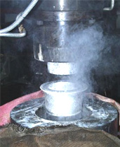
We are a leading forging company consistently delivering quality forged products since 1989. Our forging services incorporate modern equipment, skillfully engineered processes, and quality raw materials. Let's have a look at the details of a forging process. Forging is the process by which metal is heated and is shaped by plastic deformation by suitably applying compressive force. Usually the compressive force is in the form of hammer blows using a power hammer or a press.
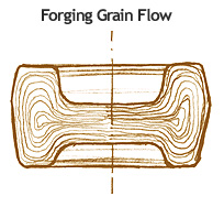
Forging refines the grain structure and improves physical properties of the metal. With proper design, the grain flow can be oriented in the direction of principal stresses encountered in actual use. Grain flow is the direction of the pattern that the crystals take during plastic deformation. Physical properties (such as strength, ductility and toughness) are much better in a forging than in the base metal, which has, crystals randomly oriented.
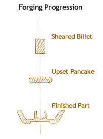
Forgings are consistent from piece to piece, without any of the porosity, voids, inclusions and other defects. Thus, finishing operations such as machining do not expose voids, because there aren't any. Also coating operations such as plating or painting are straightforward due to a good surface, which needs very little preparation.
Forgings yield parts that have high strength to weight ratio-thus are often used in the design of aircraft frame members.
A Forged metal can result in the following
- Increase length, decrease cross-section, called drawing out the metal.
- Decrease length, increase cross-section, called upsetting the metal.
- Change length, change cross-section, by squeezing in closed impression dies. This results in favorable grain flow for strong parts
Common Forging Processes
The metal can be forged hot (above recrystallization temperatures) or cold.
Open Die Forgings / Hand Forgings:
Open die forgings or hand forgings are made with repeated blows in an open die, where the operator manipulates the workpiece in the die. The finished product is a rough approximation of the die. This is what a traditional blacksmith does, and is an old manufacturing process.
Impression Die Forgings / Precision Forgings:
Impression die forgings and precision forgings are further refinements of the blocker forgings. The finished part more closely resembles the die impression.
Design Consideration:
- Parting surface should be along a single plane if possible, else follow the contour of the part. The parting surface should be through the center of the part, not near the upper or lower edges. If the parting line cannot be on a single plane, then it is good practice to use symmetry of the design to minimize the side thrust forces. Any point on the parting surface should be less than 75º from the principal parting plane.
- As in most forming processes, use of undercuts should be avoided, as these will make the removal of the part difficult, if not impossible.
- Recommended draft angles are described in the following table.
Material Draft Angle (º) Aluminum 0 - 2 Copper Alloys (Brass) 0 - 3 Steel 5 - 7 Stainless Steel 5 - 8 - Generous fillets and radius should be provided to aid in material flow during the forging process. Sharp corners are stress-risers in the forgings, as well as make the dies weak in service. Recommended minimum radiuses are described in the following table.
Height of Protrusion mm (in) Min. Corner Radius mm (in) Min. Fillet Radius mm (in) 12.5 (0.5) 1.5 (0.06) 5 (0.2) 25 (1.0) 3 (0.12) 6.25 (0.25) 50 (2.0) 5 (0.2) 10 (0.4) 100 (4.0) 6.25 (0.25) 10 (0.4) 400 (16) 22 (0.875) 50 (2.0) - Ribs should not be high or narrow, this makes it difficult for the material to flow.
Tolerances:
- Dimension tolerances are usually positive and are approximately 0.3 % of the dimension, rounded off to the next higher 0.5 mm (0.020 in).
- Die wear tolerances are lateral tolerances (parallel to the parting plane) and are roughly +0.2 % for Copper alloys to +0.5 % for Aluminum and Steel.
- Die closure tolerances are in the direction of opening and closing, and range from 1 mm (0.040 inch) for small forgings, die projection area ≤ 150 cm2 (23 in2), to 6.25 mm (0.25 inch) for large forgings, die projection area > 6500 cm2 (100 in2).
- Die match tolerances are to allow for the shift in the upper die with respect to the lower die. This is weight based and is shown in the following table.
Material Finished Forging Weight
Trimmed kg (lb)< 10
(< 22)< 50
(< 110)> 500
(> 1100)Die Match Tolerance
mm (in)Aluminum, Copper Alloys, Steel 0.75 (0.030) 1.75 (0.070) 5 (0.200) Stainless Steel, Titanium 1.25 (0.050) 2.5 (0.100) 6.5 (0.260) - Flash tolerance is the amount of acceptable flash after the trimming operation. This is weight based and is shown in the following table.
Material Finished Forging Weight
Trimmed kg (lb)< 10
(< 22)< 50
(< 110)> 500
(> 1100)Die Match Tolerance
mm (in)Aluminum, Copper Alloys, Steel 0.8 (0.032) 3.25 (0.125) 10 (0.4) Stainless Steel, Titanium 1.6 (0.064) 5 (0.2) 12.5 (0.5)
A proper lubricant is necessary for making good forgings. The lubricant is useful in preventing sticking of the workpiece to the die, and also acts as a thermal insulator to help reduce die wear.
Press Forgings:
Press forging use a slow squeezing action of a press, to transfer a great amount of compressive force to the workpiece. Unlike an open-die forging where multiple blows transfer the compressive energy to the outside of the product, press forging transfers the force uniformly to the bulk of the material. This results in uniform material properties and is necessary for large weight forgings. Parts made with this process can be quite large as much as 125 kg (260 lb) and 3m (10 feet) long.
Upset Forgings: Upset forging increases cross-section by compressing the length, this is used in making heads on bolts and fasteners, valves and other similar parts.
Roll Forgings:
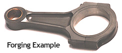
In roll forging, a bar stock, round or flat is placed between die rollers which reduces the cross-section and increases the length to form parts such as axles, leaf springs etc. This is essentially a form of draw forging.
Swaging:
Swaging a tube or rod is forced inside a die and the diameter is reduced as the cylindrical object is fed. The die hammers the diameter and causes the metal to flow inward causing the outer diameter of the tube or the rod to take the shape of the die.
Net Shape / Near-Net Shape Forging:
In net shape or near-net shape forging, forging results in wastage of material in the form of material flash and subsequent machining operations. This wastage can be as high as 70 % for gear blanks, and even 90+ % in the case of aircraft structural parts. Net-shape and near-net-shape processes minimize the waste by making precision dies, producing parts with very little draft angle (less than 1º). These types of processes often eliminate or reduce machining. The processes are quite expensive in terms of tooling and the capital expenditure required. Thus, these processes can be only justified for current processes that are very wasteful where the material savings will pay for the significant increase in tooling costs.
Please send us your queries or requirements on:
sales@indiaforging.com- soumil@indiaforging.com
Email:
- +91-98817-01007
- +91-253-2310221 / 2310275
Phone:
-
Aress High Duty Forgings Pvt. Ltd.
Address:
- E-27, MIDC, Malegaon, Sinnar, Nashik - 422103
Factory:
-
Unit No. 3, 1st Floor, Shivneri,
Next to Ramdas Colony Garden,
Canada Corner, Nashik - 422005


